CONNECTOR DESIGN
Final Design of Enclosure:
Overview
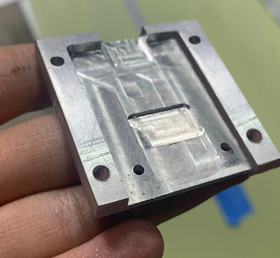
During the Summer of 2020 I worked in De-Ice, a startup located in Somerville, researching and developing a novel and functioning connector for the company’s heating cable aircraft system.
My job was to research and develop from scratch a novel and functioning connector for the company’s heating cable aircraft system. I was able to ensure that the prototypes were electrically and mechanically stable by using VNAs, thermal cameras, and multimeters. In order to manufacture the initial prototypes I used a 3D printer and then for the final few versions I machined the metallic connector with a CNC and manual mill.
The trace in the stripline that conducts electricity is made out of aluminum and since it is not possible to solder aluminum, an alternative mechanical method for connection had to be created.
Motivation
Goal
-
Create a method to reliably connect bare striplines to a coax connector (SMA) for lab use.
-
Inform Times Microwave (the company that will manufacture the connectors in mass production) on different approaches for the final design of the connector enclosure
-
Design and test methods to make good electrical and mechanical contact from the aluminum shield/trace to a coax connector piece.
-
Design and test methods to make numerous connectors that are both easy and reliable for lab use.
Process
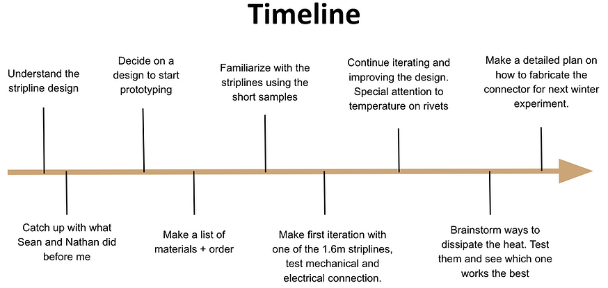
Process:
1. Understand the configuration of the striplines in order to be able to make the due modifications (what is in each layer, how much can the striplines bend before tearing, materials, etc.). Catch up with what my supervisors had already done before I was hired and learned from their finding.


2. Brainstorm ideas on different connector designs (one of them was using rivets and a PCB to ensure a secure connection).


3. Select the best ones and order materials needed to start testing/prototyping.
- Rivets: https://www.mcmaster.com/97517A470.
(Drill bit size: 2.0mm)
-
Decide between sizes
-
Correct length for material thickness
- Drill Bit 2mm (0.0787” decimal equiv.)
https://www.mcmaster.com/2841A95
- Rivet Gun https://www.mcmaster.com/6659A21


4. Familiarize myself with the short stripline samples and with the rivets. Find out which is the most efficient and reliable way to connect the striplines with the PCB board and connector enclosure: Which rivet size is the best one? In what way should the rivets be inserted? Any tricks to avoid the trace from tearing?

5. Select the best ones and make initial prototypes for the connection with the copper clad (in the future this will be replaced with a PCB). Find best and most efficient way to prep the striplines for said connector designs (for the rivets, I had to find a way to drill a hole on the 3mm wide traces without tearing them).
-
Avoid shorts in the connector itself
-
Avoid shorts between trace and aluminum sheet
-
Make sure rivets are offering a good mechanical and electrical connection

6. Design in SolidWorks an enclosure that will help in the stability of the stripline + copper-clad connections. 3D print them to test them. Iterate on the designs and modify them accordingly (for example, I added a "pressure strip" for stress relief).


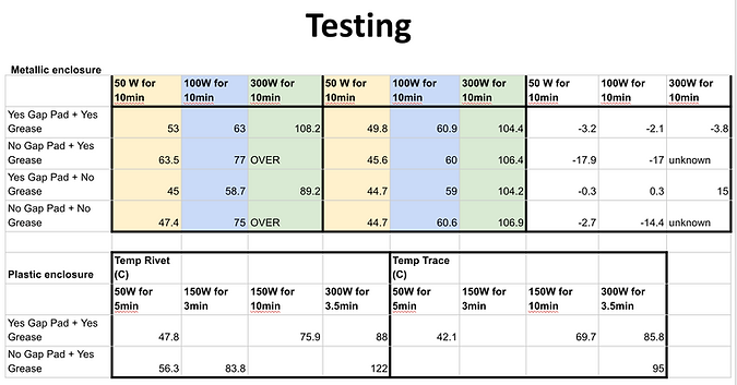
7. Ensure that the prototypes are electrically and mechanically stable by using VNAs, thermal cameras (special attention to any hotspots in the rivet connections), and multimeters. Be organized and have a labeling system to track the results.


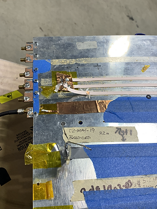
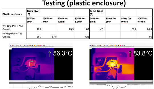

8. CNC machine final design of metallic connector enclosure and test it. Try different ways to reduce the overheating of the system: using a metallic enclosure, gap pads, using more rivets to distribute stress, conductive grease, etc.). Test them!




Secondary project:


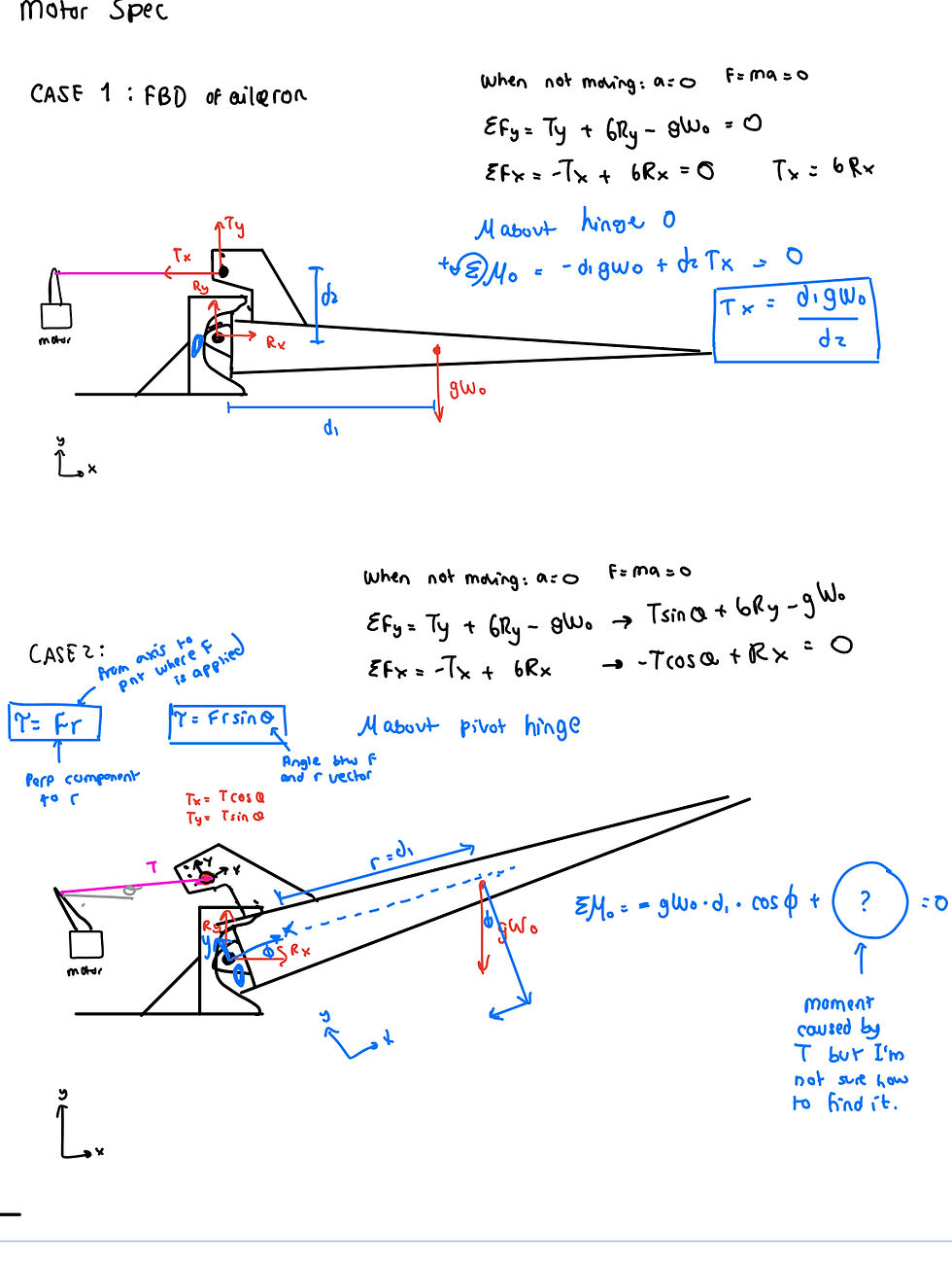

Designing an aileron stand that would showcase in the demo how will the striplines be aligned to ensure that the cables do not interfere with the rotation of the wings. Using SolidWorks I was able to CAD a replica of the aileron of an AirBus A320 with the approximate dimensions and design a way in which we could attach the aileron to a table while still allowing people to see the cables on the back (by using brackets for the support and a transparent sheet). I also spec a motor that would be able to lift the aileron automatically.
